Describe it in the customer’s words
The starting point is a high-level description — a duty, a datasheet, an existing drawing — not a modelling session. Engineering intent goes in as intent, and the parametric model is derived from it.
Simplify R&D
From a high-level customer description — parametric design, industry-standards compliance, duty selection and manufacturability, generated build-ready in minutes. Every change recalculates physics and compliance in real time.
1500×
Faster
Engineering documentation loop — weeks compressed to minutes.
The starting point is a high-level description — a duty, a datasheet, an existing drawing — not a modelling session. Engineering intent goes in as intent, and the parametric model is derived from it.
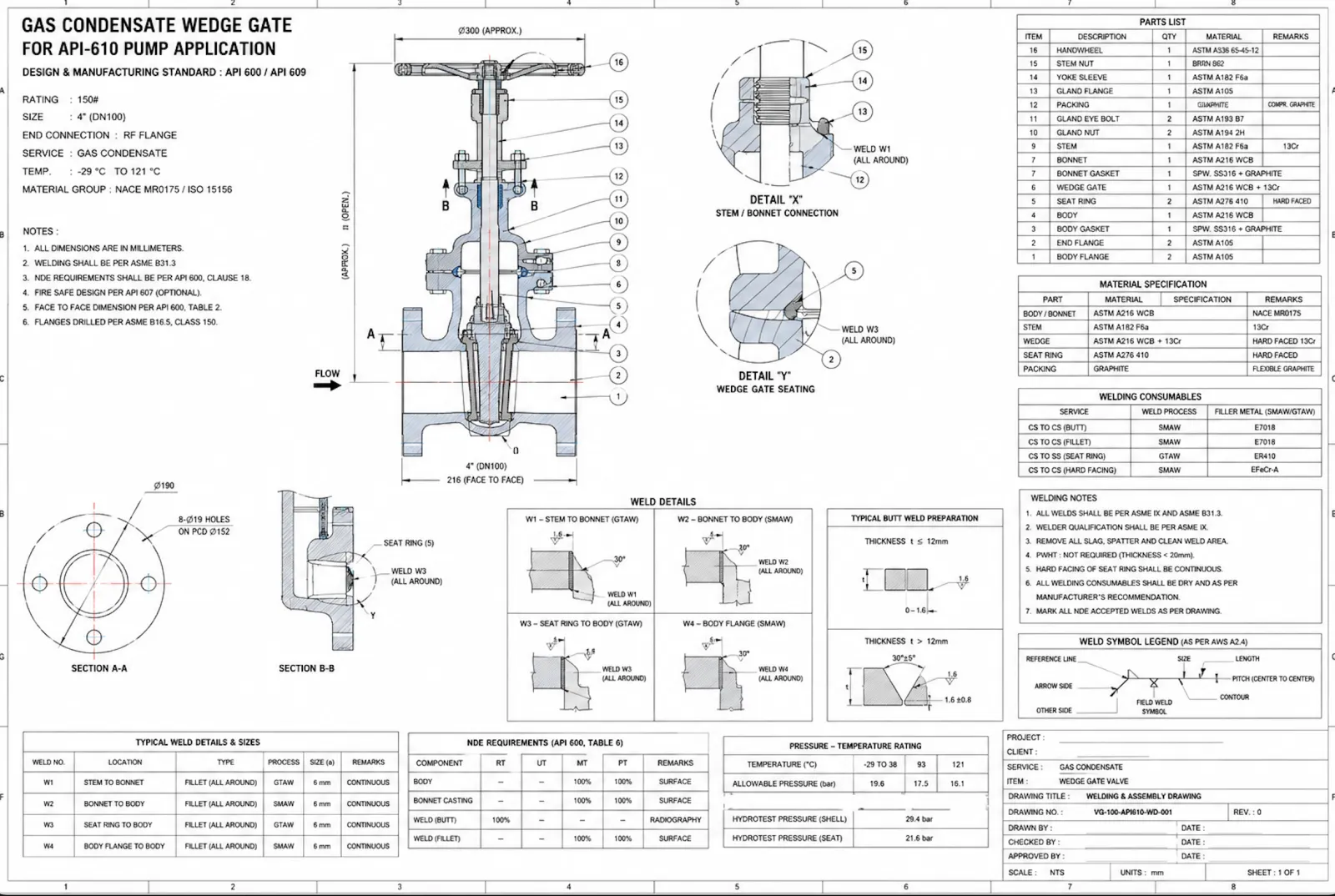
Geometry is generated from parameters rather than drawn by hand, so a variant is a change of inputs rather than a new project. The design stays a model of the rules, not a snapshot of one answer.
Industry-standards compliance and duty selection are resolved as part of generating the design, rather than checked afterwards by a reviewer working from a separate document.
Physics and compliance are recomputed in real time as inputs change, so the consequences of a decision are visible while it is still a decision — not after the drawing has been issued.
A custom variant that took weeks of drawing, checking and re-checking becomes a set of parameters that resolves in minutes — and stays correct the next time the duty changes.
01 / Why current tools aren’t enough
CAD, PLM, ERP, and simulation systems are already deeply deployed across the industry, and they do what they were built for. But the critical engineering decisions still move manually between engineering, compliance, procurement, manufacturing, QA, and operations. Every custom project generates coordination overhead that scales faster than headcount.
Multiphase flow, cavitation, fatigue, thermal cycling, sour service — the coupled conditions equipment has to survive, not captured by geometry alone.
API, ASME, ISO, NORSOK, DNV, PED — plus customer specs, MTRs, NDE reports, and traceability dossiers that now consume a large share of every project.
CNC, welding qualifications, heat treatment, forging, and casting each impose hard constraints on geometry, tolerances, and materials. Ignore them and rework lands on the shop floor.
02 / The ParaEnergy approach
Design intent, compliance rules, manufacturability limits, and simulation run in one connected loop. Your teams build in real time instead of coordinating handoffs between tools that don’t talk to each other.
03 / The unified workflow
Stage 1 · Engineering Design
Parametric CAD with engineering rules baked in.
Define the equipment by intent — flow, head, materials, service. The geometry follows.
Stage 2 · Simulation & Validation
Multi-physics, on the same model.
Stage 3 · Manufacturability
CNC, welding, heat treatment, forging & casting — from one source of truth.
04 / Capabilities
Model pumps, valves, pressure vessels, heat exchangers, and the rest of your flow-equipment portfolio from intent — service conditions, materials, sizing, code requirements. Geometry follows the rules, not the other way around.
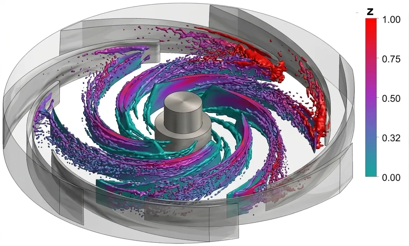
Stress, thermal, fatigue, multi-physics load cases — run on the same parametric model your CAD team produced. Validate before manufacturing handoff.
05 / Why it works
ParaForge isn’t just a UI on top of three tools. It’s a unified data and security model engineered for energy-grade equipment work.
Pillar 01
A purpose-built foundation model trained on pump, valve, and flow-equipment engineering — service conditions, standards (API, ASME, ISO, NORSOK, DNV), materials, and manufacturability constraints. Not a generic LLM bolted onto CAD: a model that already speaks your domain.
Pillar 02
Specialised agents handle CAD authoring, simulation setup, manufacturability checks, and documentation. They coordinate on the same parametric model, hand work off cleanly, and stop when an engineer needs to decide.
Pillar 03
Automated parameter setup (mesh sizing, boundary conditions, materials) and guided design-space exploration replace days of manual prep with minutes. The platform reuses prior runs, ranks variants, and tells the engineer where to look next — not just "here is one result."
Pillar 04
CNC, welding, heat-treatment, forging, and casting checks run on every revision against the same parametric model. No re-import, no offline DFM review — issues surface while the design is still cheap to change.
Bring one custom enquiry you'd normally spend weeks on. We'll turn it into a build-ready, compliance-checked, priced design — live. Then you decide.